Electronic Lighting Transformers
I tried measuring the output of a halogen downlight power supply (“electronic transformer”) with a multimeter and got nothing, or very low values, on DC or AC mode, despite the light working. I was curious so investigated what was going on.
Another strange observation was that measuring the current on the output with a DC clamp meter gave a reading, which then persisted when the supply was switched off. I suppose that means that the clamp was getting magnetised.
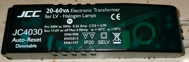
The driver is a JCC JC403, but looking it up, the output seems to be common for this type of device. Notably, it is dimmable, which explains some of the weirdness of the output.
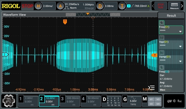
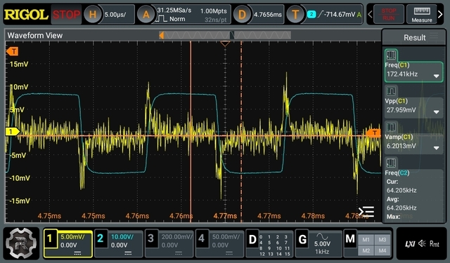
The blue traces are the output voltage. The zoomed in section is somewhere in the middle of the main part output burst. The yellow trace is from a current transformer clipped around the mains input. It is connected to an oscilloscope probe and I made no effort to terminate it in any particular way, so it only gives the general shape of the input current, if anything.
It’s a high frequency (64 kHz is shown on oscillogram above, but it’s not very stable), square wave, generated from the input sine wave, apparently without smoothing capacitors on input or output. The lack of input storage capacitor has the interesting effect of making the switcher only start up when the voltage rises enough on each half cycle of the input. Therefore, a dimmer which cuts off part of the wave will reduce the average output power.
I don’t know why there are some shorter bursts during the lower parts of the input cycle. Maybe there is some small input capacitor that charges up enough for short bursts?
The wave has no significant DC component, so does not register on a DC meter. The AC output is at too high a frequency for most multimeters (although it is readable by some). Unlike a VFD, which uses PWM to produce a waveform that filters down to a lower frequency AC output, e.g. 50 Hz, this driver produces no significant lower frequency component.
Input current measurements
The following is mostly notes to myself.
Current measurement on mains supply to driver, using Hioki mA range. Around 250V, 50Hz input.
No load: 3.3 mA. 59.146 Hz. LED “3.6W”. 32.8 to 32.9 mA, 4.6 kHz. Buzzing noise from bulb. 20W halogen: 81.9 mA, 61.939 Hz.
CT measurement was about 1.1V (RMS) from Hioki, if I remember right.
Hioki input impedance, measured with another multimeter, on DCV mode: 10.96 M Ohm. On AC get OL. Cap coupled? DC+AC mode: 1M Ohm. Hm.
CT says 100A:50mA. www.yhdc.co